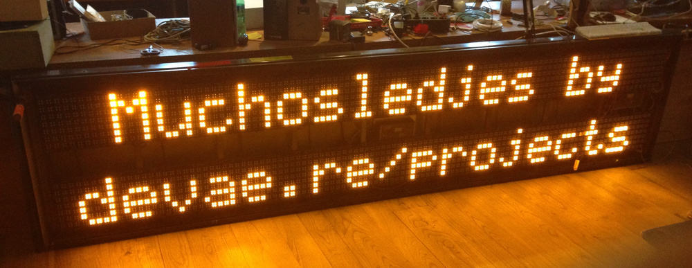
Muchosledjes: reverse engineering a led matrix
I recently scored a large full weatherproof 16 characters, 2 lines mono color led screen. Unfortunately the built in driver board was totally crap: You could only upload text to it via proprietary software, and there was no api of any sorts available. I wanted more, so I decided to reverse engineer the led panels, and come up with a new driver module.
The basic structure of the display
The original display consists of 16 daisy chained led boards, and there are two PSU’s to power the thing. Furthermore there are a bunch of fans, another small psu to power the processor board and the processor board itself. This last board communicated over RS-232 with a computer that runs (crappy) proprietary software. Every board has an array of 7x14 pixels, every pixel consisting out of 4 leds on the same control lines. A character is 20 cm high.
Reverse engineering
I wanted more than the software could do so I had two choices:
- Reverse engineer the protocol between the computer and the processor board
- Reverse engineer the hardware, and come up with a new driver board
I opted to go with the second option, so I puled out one of the display panels and started following traces and looking up data sheets.
I quickly found out the boards are pretty simple: There are two banks of shift registers on each board:
one that contains the data for the horizontal lines, and one for the vertical data lines. Apart from that every board had some tri-sate buffers for the control signal.
The pinout for the display pannels can be found on github
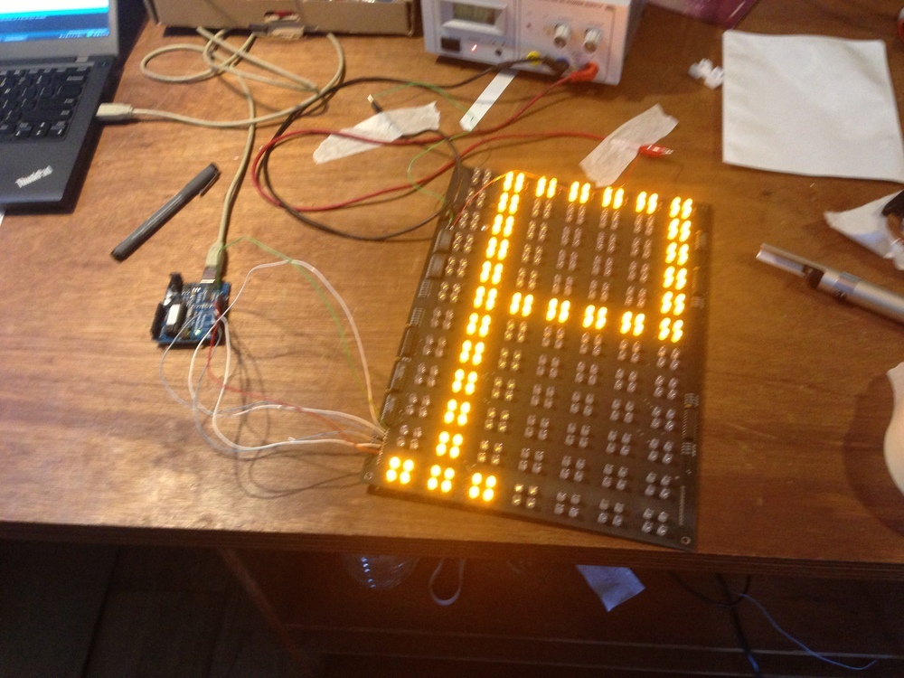
I hooked up an arduino to the data lines, and after some tinkering I could display my first real graphic:
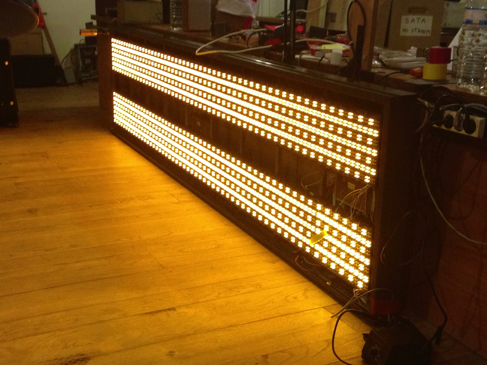
From here on out things went rather quickly. I placed the panel pack in to the display and tried to get some sensible stuff on the entire screen. I started out by displaying some simple patterns, and experienced some weirdness: when I displayed certain patterns the second half or the entire display would start to flicker. I turned out that this was because I turned on all the lines instead of scanning over them, and the power supply could not supply enough current for this, so it started to shut down en restart. Once I figured that out I started to always scan the lines, and I could display nice patterns.
After some experimenting it was clear an arduino was not going to cut it to drive this board, so I moved to a raspi. The downside to this was that I had to use level shifters, but since all data lines are monodirectional, a couple of transistors did the trick.
Writing the raspi drivers
I slightly abused SPI to shift the data in to the shiftregisters controlling the collums, so I gave python a tiny chance to be able to scan the display fast enough. I started out by writing some drivers in python, but as expected the code was not fast enough: the display looked horrible. To get a higher and more constant refresh rate I rewrote the code in C, and it was better, but not quite what I was hoping for yet. The solution to this was to give the code real time priority, which can be achieved with the following code snippet:
memset(&sp, 0, sizeof(sp));
sp.sched_priority = sched_get_priority_max(SCHED_FIFO);
sched_setscheduler(0, SCHED_FIFO, &sp);
mlockall(MCL_CURRENT | MCL_FUTURE);
After adding this, the display was very stable and fluid.
Because I din’t want to write all of my code in C, I made the C code listen on UDP for new frames that it would then display on the board.
The frame generator
I wrote a python program to generate the frame data. I started of by displaying three characters: ‘A’, ‘B’ and ‘C’
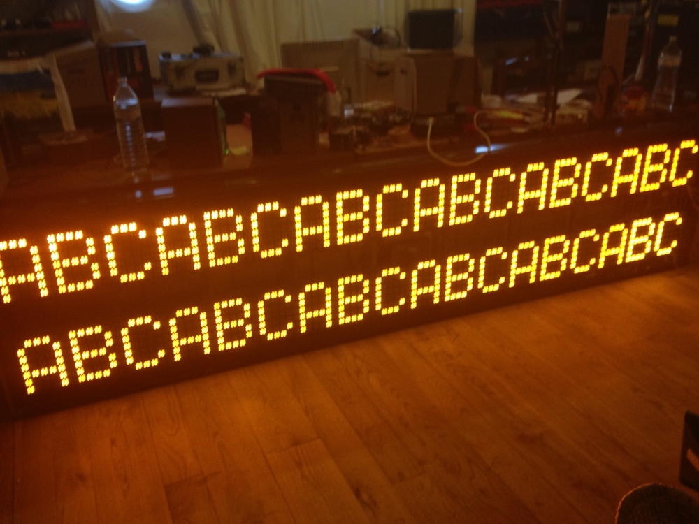
After this I found a font for led displays, and wrote a simple python script to convert the font to something that was compatible with my code. Now I could display the entire alphabet \o/
The font is in a separate file and looks like this:
! 00100 00000 00100 00100 00100 00100 00100
" 00000 00000 00000 00000 01010 01010 01010
# 01010 01010 11111 01010 11111 01010 01010
$ 00100 11110 00101 01110 10100 01111 00100
% 00011 10011 01000 00100 00010 11001 11000
& 01101 10010 10101 01000 10100 10010 01100
' 00000 00000 00000 00000 01000 00100 01100
First on a line is the ASCII character, followed by the data for every of the seven rows of the display.
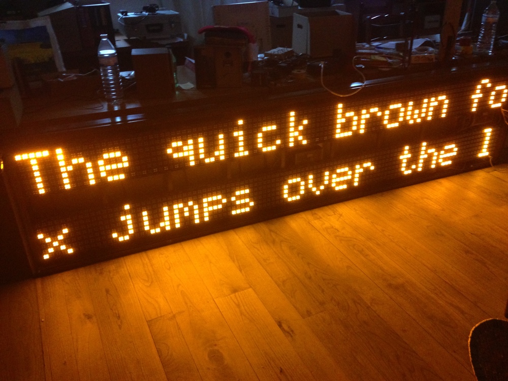
Next I wrote code for some effects like scrolling text, auto centering text, blinking text and setting the text on both lines independently. I also wrote a couple of lines to make it possible to display images on the screen.
Tweet to the display!
Inspired by Juerd and his ledbanner I made the frame generator listen on UDP for text messages to display on the display. Each message should start with a number indicating the priority, followed by the text to be displayed. The frame generator will first display all received messages with priority 0, next the ones with priority 1 etc. etc.
I wrote two applications for this: one that can follow people and topics on twitter, and one that receives email. The twitter application allows you to follow different topics and users with different message priorities, so you can have a ‘background’ and a ‘foreground’ stream of messages. It also filters out all tweets containing ‘RT’, and removes all urls. The email client uses the subject of the mail as message, and only accepts messages when the body contains a shared secret.
Power usage
When no leds are lit the display uses about 23 W, when all led’s are on (scanning) the display uses up to 200 W.
Current state of the project
2014-08-26: The raspi driver, frame generator, email and twitter followers are now working.
Known bugs
-
When following a very active twitter stream the display starts to flicker because the refresh rate becomes to slow / unstable. Possible solutions:
- Let an external board handle the scanning of the display
- Add a second raspi just for the scanning of the display and connect them via ethernet
- Port the code a faster board
I’m currently planning to port the code to a beagle bone black, and see whether or not it runs smoothly.
-
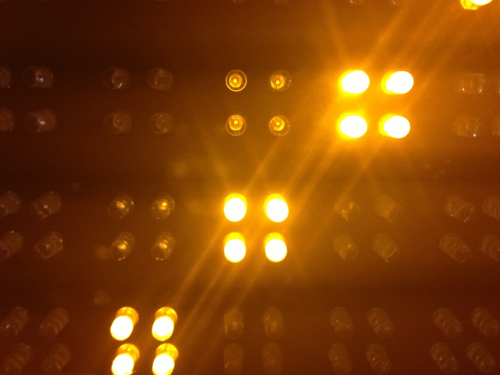
The pixel above a lit pixel is dimly lit
This is probably caused because I’m pulling the Turn on the display line high all the time, and the shift registers for the rows update quicker than the ones for the lines. I think that pulling the Turn on display low while changing over to the new data to show will solve this issue.
Future features
- Receive messages over sms
- Add a cellular modem to it, so we can follow twitter everywhere
- Make a nice config file system to set what messages to display
- Make it possible to interrupt the normal cycle to display incoming messages
- Add a relay to cut the power to the power supplies if the display is inactive for a certain time
More info
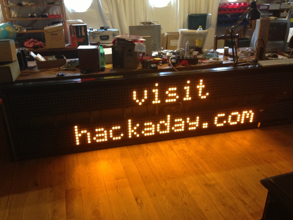
All of the code I wrote is on github. The project got featured on hackaday.com, there is an intresting discussion about the power usage in the comments.
Mandatory hackaday shot