Dumbledore, another light controller
My dad had some specific requirements for the lighting system in our new house. He wanted a stable light control system that was expandable and had the following features:
- Pushing a light button shortly should toggle the corresponding lights
- Holding any light button for a longer time, should turn off all lights on that floor
- Holding any light button even longer, and all lights in the house should turn off.
Hardware rundown
For the project I designed an atmega based board that can control up to eight lights. Furthermore every Bord has a zone bus and an all bus. By connecting the boards using this bus system, you can create zones. For more explanation on how this works, see the software section.
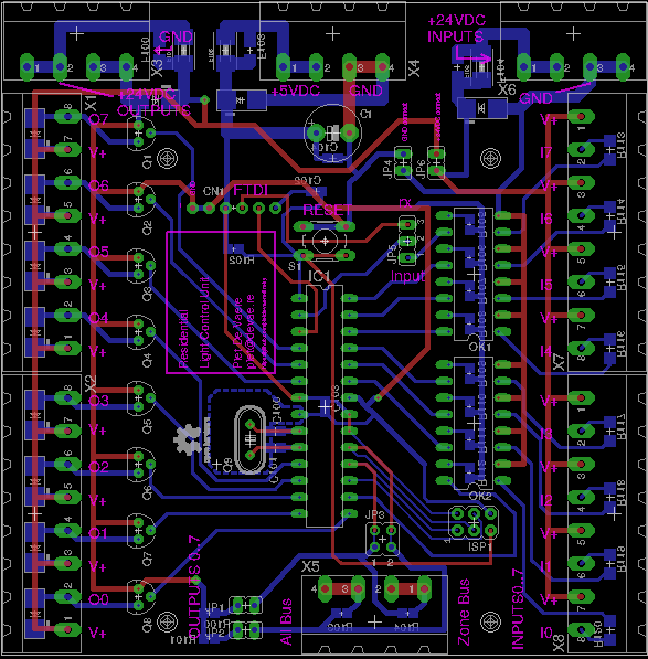
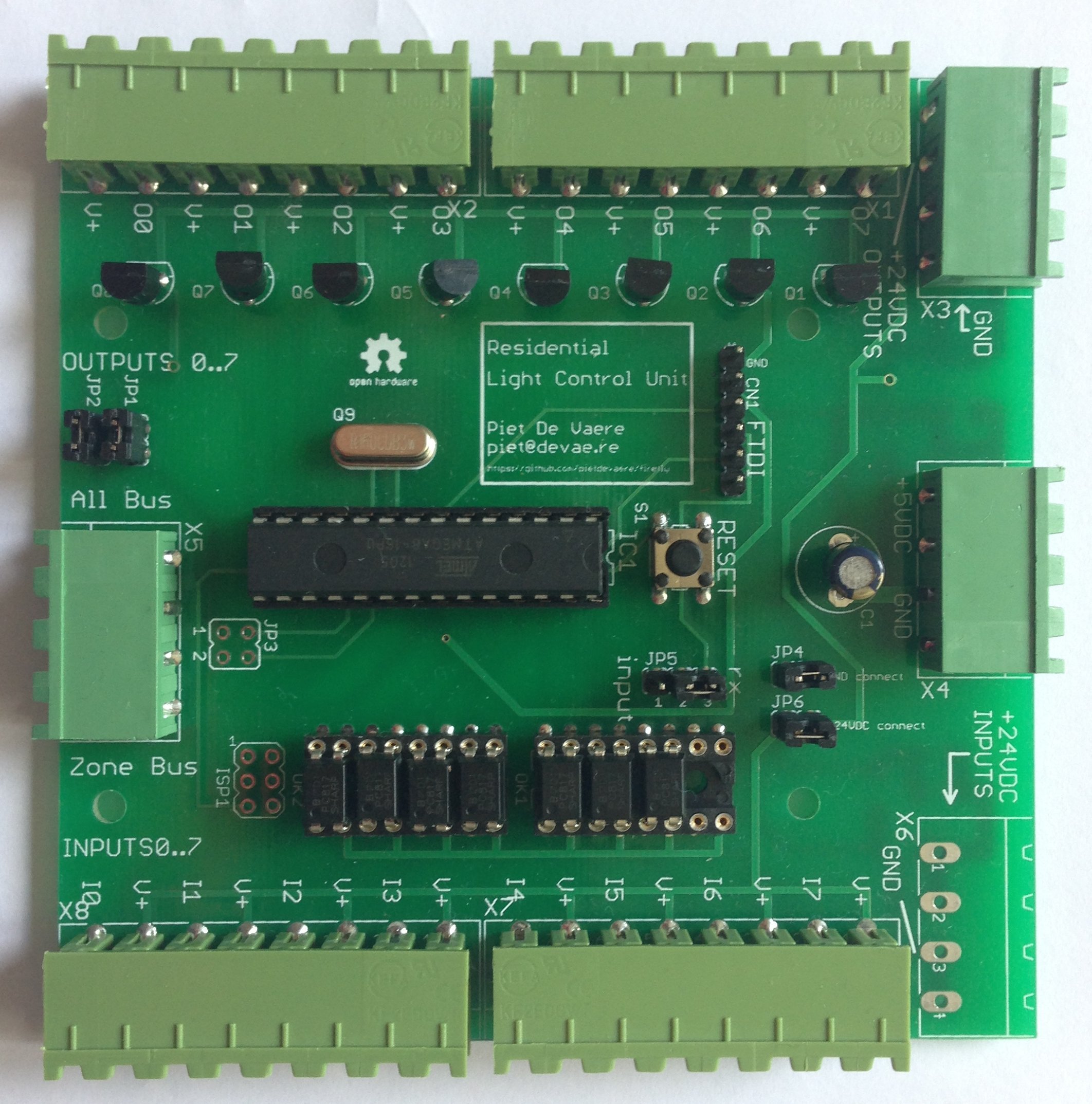
The Dumbledore board layout.
The board consists of a couple of base elements:
- An atmega8 doing the main processing
- An array of optocouplers to eliminate any EMI
- An array of transitors to drive external relays
- Power input terminal blocks
- Bus terminal blocks
The rev. 0 board had two small issues:
- The rx pin on the micro was not pulled down. This is necessary when using the Arduino bootloader on an atmega 8 (which I’m using to make it easy for others to tweak the code). If you don’t pull the pin down, the bootloader keeps waiting for serial data forever.
- I forgot to add pull down resistors om the gates of the mosfets. During normal operation this is not a problem, but when booting the I/O pins are all in high impedance mode, and there is a floating voltage on the pins.
Both of these issues could be solved by getting rid of the bootloader, but since I want it to be easy to change the code I decided not to do this. I bodged some resistors on the board and everything works fine now. Because I only need a few board for personal use, I’m probably not going to make a patched version, but just bodge the resistors on all the board I need.
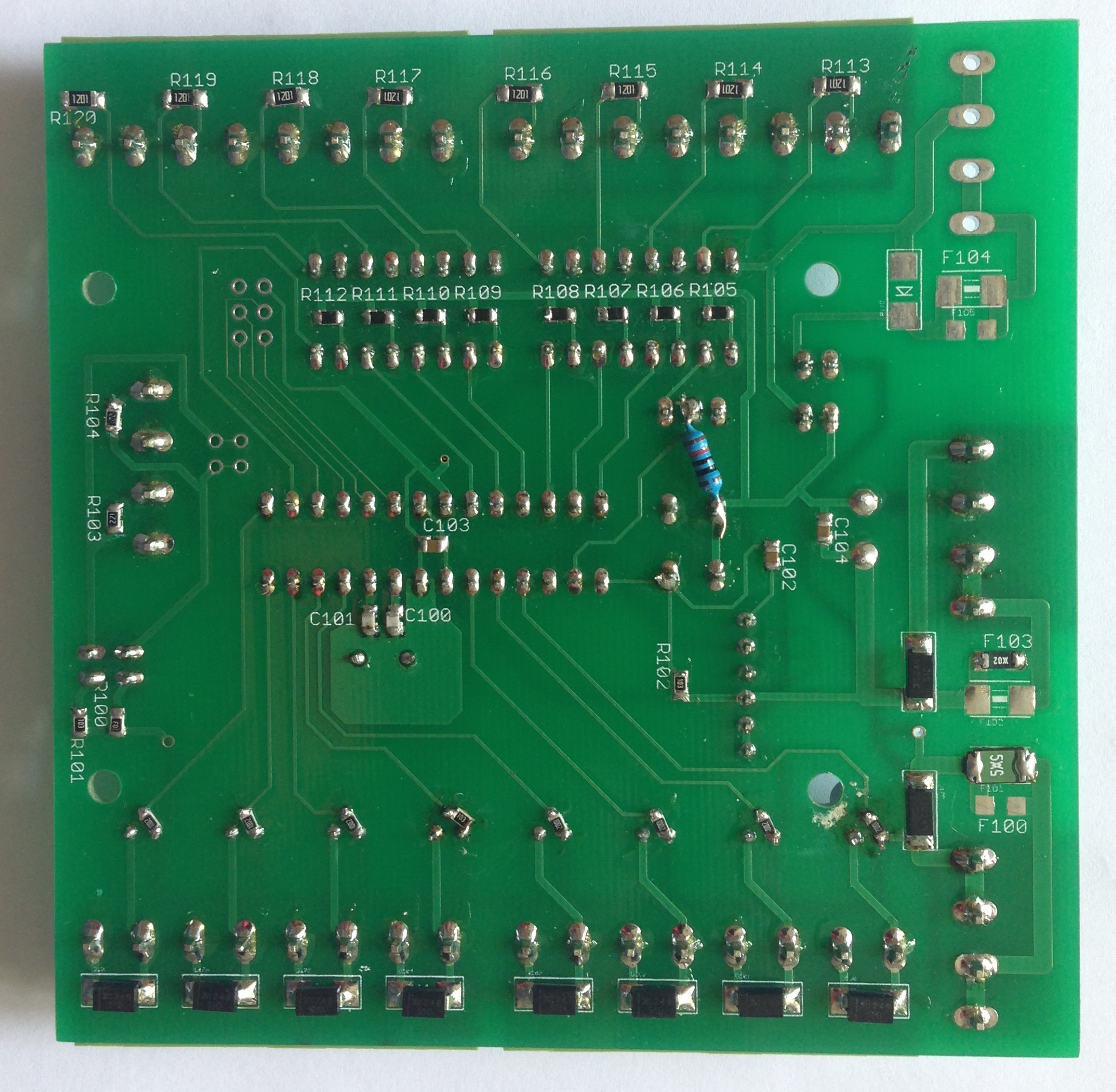
The bodged resistors
Software
The software does the following things:
- Time the length of a detected button press, and decide what do do:
- length < debouncetime: Do nothing
- debouncetime < length < zonetime: Toggle the corresponding output
- zonetime < length: Turn off all lights on this board, and write the zone pin high
- alltime < length: Turn off all lights on this board and write the all pin high
- Read out the state zone and all pins: if the zone or all pins are high for longer than the debouncetime, turn of all lights on this board
The inputs pins are always in high impedance mode with the internal pull ups enabled.
When we are not sending out a signal on one of the buses, they are in high impedance mode, with the internal pull up resistor disabled.
For the zone and all off functions to work properly, all boards should be connected via the all bus, and all boards in the same zone should be connected via their zone buses.
The bus system
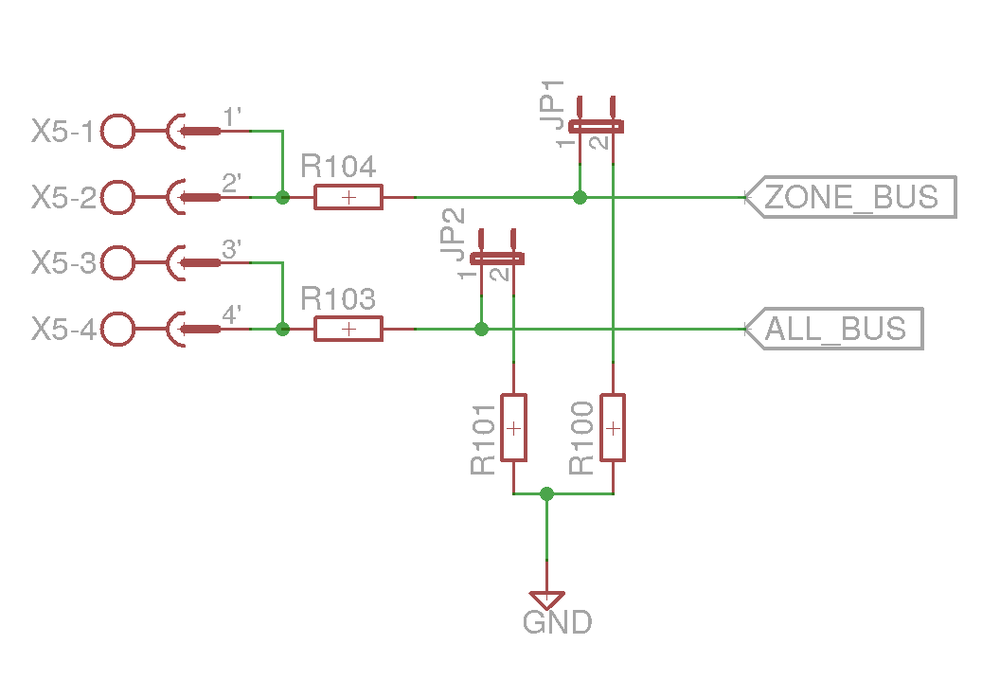
I decided not to use a fancy systems like I2C or SPI, but go for a super simple solution: Every bus has two resistors around it: a pull down, and a current limiter. The pull down resistor is connected via a jumper, so you don’t get problems with the equivalent pull down resistance becoming to small when adding a lot of board to a bus. Just install the jumper on one board of every zone, and do it for one board on the all bus. The current limiter is just there for short circuit protection.
When idle all Pins are in high impedance mode (pull up disables), and are waiting for the pin to become high. To send out a signal the pin is changed to high.
The test setup
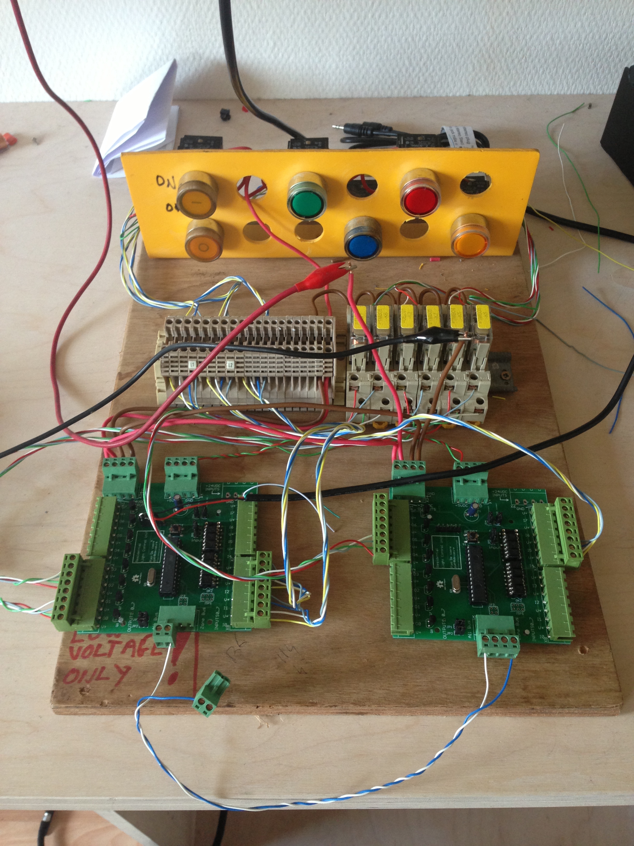
I hooked up some buttons, relays and lights up to two boards. Video of the boards in opperation comming soon (read: sometime).
Current status
2014-08-25: The boards and components are ordered and on their way to me for assembly. The base for the software is ready and I will finish it up when the boards are assemblies.
2014-09-16: Two of the bords are fully assembled and tested. Once the other ones are assembled the system can be installed.
Schematics and source code
You can find the code and schematics (in eagle format) on github
Note: This project used to be named firefly